|
Last afternoon/evening we were at the hoverport making changes described
a Construction Report 2000-10-17 but weren't
able to finish all of them because of the early darkness.
|
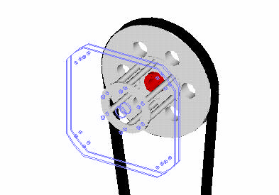 |
| Propeller plates are shown in wireframe and missing from this image are bolts (from plates through pulley), thrust shaft and shorter tubes between two plates and of course drive stand. Center holes in plates have tight fitting to shaft, so tight we had to warm the plates to remove them. Bolts are M10 (~3/8") and there are six of them as number of tubes and holes show. Red component in the center of pulley is TOLLOK friction clamping element which i used. They don't need key way or taper holes and hold pulleys in place also axially. |
| Pictures of drive installation can be found at Construction Reports 2000-05-14. At the bottom of that page is bearing housing for the drive shaft where one of the blades hit at 2000-09-27 |